
| Model | QGCS-Q1000 | QGCS-Q3000 | QGCS-Q4000 | QGCS-Q5000 |
| Size | DN15-DN100 | DN15-DN150 | DN15-DN200 | DN15-DN300 |
| Max Flow(m3) | 1000 | 3000 | 4000 | 5000 |
| Area(LxWxH) m | 10 x 4 x 3.5 | 12 x 6 x3.5 | 16 x 6 x 3.5 | 18 x 8 x 3.5 |
| Consumption(KW) | ≤32 | ≤80 | ≤107 | ≤132 |
| Uncertainty | ≤0 . 33% | |||
Accuracy |
Absolute pressure transmitter: 0.075% ~ 0. 1% Temperature sensor: 0.2% Humidity sensor: 2% Critical flow nozzle: 0.2% |
|||
| Collect Signal | Pulse, 4~20 mA | |||
| Wetted Parts | SS304 | |||
| Flow | Min standard: 0.016 m3/h, normal standard: Qm=2n | |||
| Working Environment | Atmospheric pressure: 86 ~ 104KPa Relative humidity: 40% ~90%RH | |||
| Design Standard | lSO 9300:2005, GB/T 21188-2007 | |||
.png) |
.png) |
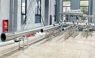
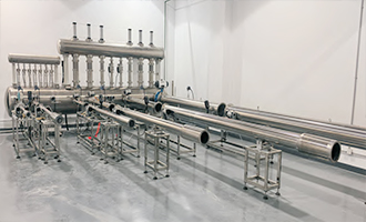
| QGCS-Q1000 | QGCS-Q3000 |
.png) |
.png) |
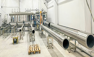
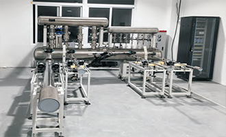
| QGCS-Q4000 | QGCS-Q5000 |
| QGCS-Q1000 | DN50/DN100 |
| QGCS-Q3000 | DN25/DN50/DN80/DN100/DN150 |
| QGCS-Q4000 | DN50/DN80/DN100/DN150/DN200 |
| QGCS-Q5000 | DN50/DN100/DN150/DN200/DN300 |
|
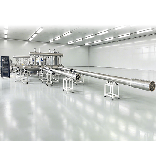
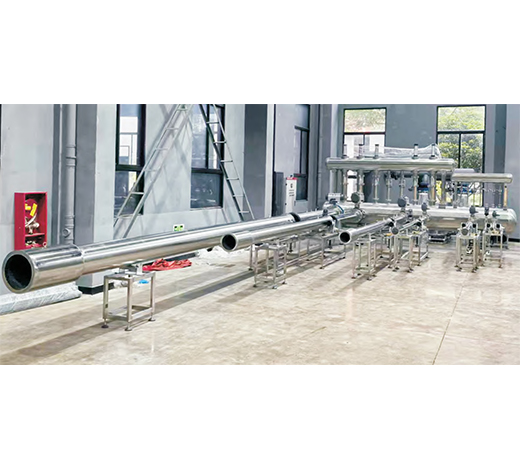
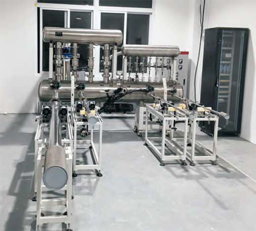
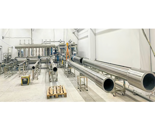
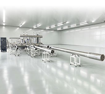
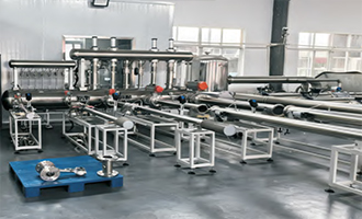
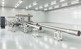
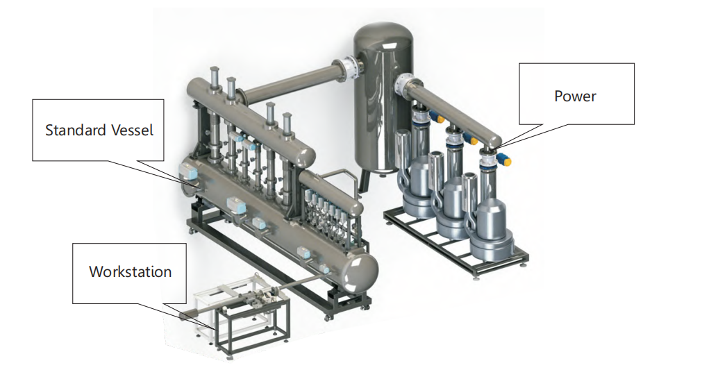
It consists of a stagnation vessel, a large-area vacuum vessel, a small-area vacuum vessel, standard flow meters (Critical Flow Venturi Nozzles), vacuum valves, connecting pipelines, and structural component
|
|
Pressure Measurement: The pressure data upstream and downstream of the Critical Flow Venturi Nozzles are respectively collected from the stagnation vessel and the large/small vacuum vessels.
|
|
Modular Design: The entire standard device module features a skid-mounted design, which facilitates easy installation and future expansion.
|
|
Installation Method: The Critical Flow Venturi Nozzles are installed on the stagnation vessel using the upstream large-space method (or "stagnation chamber" method)
|
.png)
| 1. Self-diagnostic function | 2. Customizable calibration data format |
| 3. Adaptive power system | 5. Selectable data forms / Optional data templates |
| 6. On-site verification of nozzle coefficient / Field calibration of nozzle coefficient | 4. Arbitrary matching of flow points / Flexible flow point matching |