Products
Coriolis Mass Flow Meter

Coriolis Mass Flow Meter

Flow accuracy: ±0.2% Optional ±0.1%
Diameter: DN3~DN200mm
Flow repeatability: ±0.1~0.2%
Density measuring: 0.3~3.000g/cm3
Density accuracy: ±0.002g/cm3
Introduction
Application
Technical Data
Installation
Introduction
PHCMF Coriolis mass flow meter is designed according to micro motion and Coriolis principle. It is a leading precision flow and density measurement solution offering the most accurate and repeatable mass flow measurement for virtually any process fluid, with exceptionally low pressure drop.
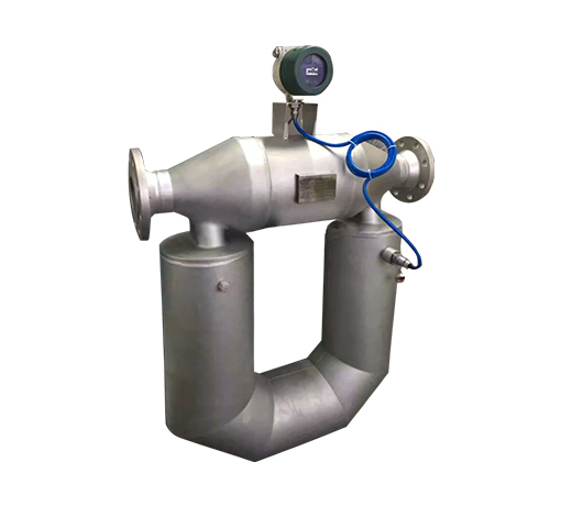
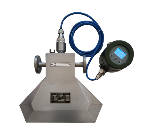
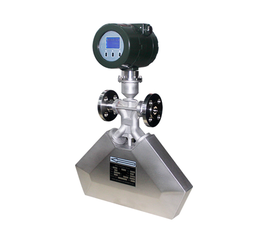
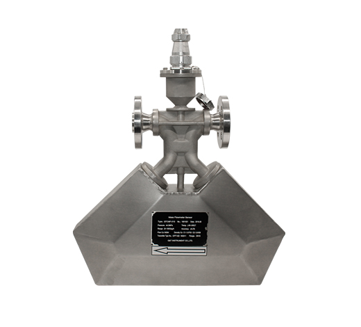
The Coriolis flow meter worked on the Coriolis effect and was named. Coriolis flow meters are considered to be true mass flow meters because they tend to measure mass flow directly, while other flow meter techniques measure volume flow.
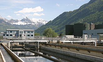
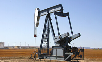
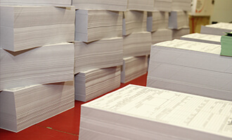
Besides, with batch controller, it can directly control the valve in two stages. Therefore, Coriolis mass flowmeters are widely used in chemical, pharmaceutical, energy, rubber, paper, food and other industrial sectors, and are quite suitable for batching, loading and custody transfer. 
 
Advantages
Coriolis Type Flow Meter Advantages
It has high measurement accuracy, standard accuracy 0.2%; And the measurement is not affected by the physical properties of the medium.
Coriolis type flow meter provide a direct mass flow measurement without the addition of external measurement instruments. While the volumetric flow rate of the fluid will vary with changes in density, the mass flow rate of fluid is independent of density changes.
There is no moving parts to wear and need to be replaced. These design features reduce the need for routine maintenance.
The Coriolis mass flow meter is insensitive to viscosity, temperature and pressure.
The Coriolis flow meter can be configured to measure positive or reverse flow.
Flow meters are operated by flow characteristics such as turbulence and flow distribution. Therefore, upstream and downstream direct pipe operating requirements and flow regulation requirements are not required.
The Coriolis flow meter does not have any internal obstacles, which may be damaged or blocked by viscous slurry or other types of particulate matter in the flow.
It can take measurement of high viscosity fluids, such as crude oil, heavy oil, residual oil and other liquids with higher viscosity.
 
Application

● Petroleum, such as crude oil, coal slurry, lubricant and other fuels.

● High viscosity materials, such as asphalt, heavy oil and grease;

● Suspended and solid particulate matter materials, such as cement slurry and lime slurry;

● Easy-to-solidified materials, such as asphalt

● Accurate measurement of medium- and high-pressure gases, such as CNG oil and gas

● Micro-flow measurements, such as fine chemical and pharmaceutical industries;

Water Treatment
Water Treatment
Food Industry
Food Industry
Pharmaceutical Industry
Petrochemical
Petrochemical
Paper Industry
Paper Industry
Chemical Monitoring
Chemical Monitoring
Metallurgical Industry
Public Drainage
Public Drainage
Coal Industry
Coal Industry
Technical Data

Table 1: Coriolis Mass Flow Meter Parameters

Flow accuracy ±0.2% Optional ±0.1%
Diameter DN3~DN200mm
Flow repeatability ±0.1~0.2%
Density measuring 0.3~3.000g/cm3
Density accuracy ±0.002g/cm3
Temperature measuring range -200~300℃ (Standard Model -50~200℃)
Temperature accuracy +/-1℃
Output of current loop 4~20mA; Optional signal of flow rate/Density/Temperature
Output of frequency/pulse 0~10000HZ; Flow signal (Open collector)
Communication RS485, MODBUS protocol
Power supply of transmitter 18~36VDC power≤7W or 85~265VDC power 10W
Protection class IP67
Material Measuring tube SS316L housing:SS304
Pressure rating 4.0Mpa (Standard pressure)
Explosion-proof Exd(ia) IIC T6Gb
Enviroment Specifications
Ambient temperature -20~-60℃
Enviroment humidity ≤90%RH

Table 2: Coriolis Mass Flow Meter Dimension


Model A B C D E NW(only sensor)
mm mm mm mm mm kg
HTCMF-020 250 448 500 89 233 17
HTCMF-025 550 500 445 108 238 17.5
HTCMF-032 550 500 445 108 240 24
HTCMF-040 600 760 500 140 245 32
HTCMF-050 600 760 500 140 253 36
HTCMF-080 850 1050 780 220 315 87.5
HTCMF-100 1050 1085 840 295 358 165
HTCMF-150 1200 1200 950 320 340 252
HTCMF-200 1200 1193 1000 400 358 350
 
Model A B C D E Nw
mm mm mm mm mm kg
HTCMF-003 178 176 250 54 244 48
HTCMF-006 232 263 360 70.5 287 8.1
HTCMF-00B 232 275 395 70.5 290 82
HTCMF-010 95 283 370 70.5 242 65
HTCMF-015 95 302 405 70.5 242 65

Table 3: Coriolis Mass Flow Meter Flow Range

Specification DN
(mm)
Flow range
(kg/h)
Zero stability, kg/h NW
(kg)
GW
(kg)
0.2% 0.15% 0.1%
QTCMF-003 3 0~96~120 0.018 0.012 0.012 8 19
QTCMF-006 6 0~540~660 0.099 0.066 0.066 12 22
QTCMF-008 8 0~960~1200 0.18 0.12 0.12 12 23
QTCMF-010 10 0~1500~1800 0.27 0.18 0.18 11 24
QTCMF-015 15 0~3000~4200 0.63 0.42 0.42 12 25
QTCMF-020 20 0~6000~7800 1.17 0.78 0.78 20 34
QTCMF-025 25 0~10200~13500 2.025 1.35 1.35 21 35
QTCMF-032 32 0~18000~24000 3.6 2.4 2.4 27 45
QTCMF-040 40 0~30000~36000 5.4 3.6 3.6 35 55
QTCMF-050 50 0~48000~60000 9 6 6 40 60
QTCMF-080 80 0~120000~160000 24 16 16 90 150
QTCMF-100 100 0~222000~270000 40.5 27 27 170 245
QTCMF-150 150 0~480000~600000 90 60 60 255 350

Table 4: Coriolis Mass Flow Meter Mode Selection

QTCMF XXX X X X X X X X X X
Caliber
(mm)
DN3mm-DN200 mm                    
Nominal
Pressure
0.6Mpa 1
1.0Mpa 2
1.6Mpa 3
2.5Mpa 4
4.0Mpa 5
Others 6
Connection Flange 1
Tri-clamp(Sanitary) 2
Thread 3
Others 4
Accuracy 0.1 1
0.2 2
Temperature  - 200℃~200℃ 1
-50℃~200℃ 2
-50℃~300℃ 3
Structure
Type
Compact/Integral 1
Remote 2
Power
Supply
AC220V A
DC24V  D
Output
Signal
4-20mA/Pulse,RS485  A 
4-20mA,HART B
Others C
Ex-proof Without Ex-proof 0
With Ex-proof 1
Process
Connection
DIN PN10 1
DIN PN16 2
DIN PN25 3
DIN PN40 4
ANSI 150# A
ANSI 300# B
ANSI 600# C
JIS 10K D
JIS 20K E
JIS 40K F
Others G
 
Installation
Coriolis Mass Flow Meter Installation
1. Basic Requirements on installation
(1)Flow direction should be in accordance with PHCMF sensor flow arrow. 
(2)Properly supporting is required for preventing tubes vibrating.
(3)If a strong pipeline vibration is inevitable, it is recommended to use a flexible tube to isolate the sensor from the pipe.
(4)Flanges should be kept parallel and their center points should be located on the same axis to avoid subsidiary force generation.
(5)Installation vertically, make the flow from the bottom up when measuring, meanwhile, the meter should not be installed on the top to prevent air getting trapped inside the tubes.
2.Installation Direction
In order to ensure the reliability of the measurement, the ways of installation should consider the following factors:
(1)The meter should be installed downward when measuring liquid flow (Figure 1), so that air cannot get trapped inside the tubes.
(2)The meter should be installed upward when measuring gas flow (Figure 2),  so that liquid cannot get trapped inside the tubes.
(3)The meter should be installed sideward when the medium is turbid liquid (Figure 3) to avoid particulate matter accumulated in the measuring tube. The flow direction of medium goes from the bottom up through the sensor.
 
Send Your Inquiry
Exported to more than 150 countries around the globe, 10000 sets/month production capacity!
Copyright © Q&T Instrument Co., Ltd. All Rights Reserved.
Support: Coverweb