Products
Electromagnetic water meter

Electromagnetic water meter

Size: DN50--DN800
Nominal Pressure: 0.6-1.6Mpa
Accuracy: ±0.5%R, ±0.2%R (Optional)
Electrode material: SS316L,HC,Ti,Tan
Ambient temperature: -10℃--60℃
Introduction
Application
Technical Data
Installation
Introduction
Electromagnetic water meter is a kind of instrument for measuring the volume flow of conductive liquid based on Faraday's principle of electromagnetic induction. It has the characteristics of wide range, low initial flow, low pressure loss, real-time measurement, cumulative measurement, bi-direction measurement, etc. It mainly uses DMA zoning, online monitoring, water loss analysis and statistical settlement of water supply mains.
 
Advantages
1 No blocking parts inside of measuring tube, low pressure loss and low requirements for straight pipeline. 
2 Variable diameter design, improve measurement accuracy and sensitivity, reduce excitation power consumption. 
3 Select suitable electrodes and liner, with good corrosion resistance and wear resistance. 
4 Full electronic design, strong anti-interference ability, reliable measurement, high accuracy, wide flow range.
Application
Electromagnetic water meter is a metering instrument specially designed for the actual requirements of water supply enterprises, specially designed for water industry, which can optimize water supply and ensure accurate water trade measurement and settlement. Practice has proved that electromagnetic water meter is the ideal choice to solve the measurement contradiction of large water users. In addition, electromagnetic water meters are widely used in chemical industry, environmental protection, metallurgy, medicine, paper making, water supply and drainage and other industrial technology and management departments.
City water supply
City water supply
Farm irrigation
Farm irrigation
Waste water treatment
Oil industry
Oil industry
Pharmaceuticals industry
Water supply and drainage
Technical Data

Table 1: Electromagnetic water meter Technical Data

Executive standard GB/T778-2018        JJG162-2009
Flow direction Positive/negative/net flow
Range Ratio R160/250/400(Optional)
Accuracy Class 1 class/2 class(Optional)
Nominal Diameter(mm) DN50 DN65 DN80 DN100 DN125 DN150 DN200 DN250 DN300
Nominal Flow Rate(m3/h) 40 63 100 160 250 400 630 1000 1600
Pressure Loss ∆P40
Temperature T50
Pressure 1.6MPa(Special pressure can be customized)
Conductivity ≥20μS/cm
Initial flow velocity 5mm/s
Output 4-20mA, Pulse
Flow profile sensitivity class U5,D3
Electromagnetic compatibility E2
Connection Type Flanged,GB/T9119-2010
Protection IP68
Ambient temperature -10℃~+75℃
Relative humidity 5%~95%
Installation type Horizontal and vertical
Electrode material 316L
Body material Carbon steel/ stainless steel (optional)
Grounding method With or without grounding/grounding ring/grounding electrode (optional)
Product Selection
Base

Wireless IOT

Wireless remote transmission of flow and pressure

Remote transmission of flow and pressure
Output / GPRS/Nbiot GPRS/ Nbiot/Pressure remote RS485/TTL
  Communication / CJT188,MODBUS CJT188,MODBUS CJT188,MODBUS
Power Supply DC3.6V Lithium battery DC3.6V Lithium battery DC3.6V Lithium battery DC3.6V Lithium battery
Structure Type Integral and remote type Integral and remote type Integral and remote type Integral and remote type
Units Accumulated flow:m3
Instantaneous flow:m3/h
Accumulated flow:m3
Instantaneous flow:m3/h
Accumulated flow:m3
Instantaneous flow:m3/h               Pressure:MPa
Accumulated flow:m3
Instantaneous flow:m3/h
Application Can replace water meter, ultra-low pressure loss, no wear Real-time and effective remote meter reading Realize pipe network pressure monitoring and become an intelligent terminal for metering and monitoring to provide information for the water supply enterprise informatization construction (SCADA,GIS,modeling, hydraulic model,scientific dispatch)  Wired remote

Table 2: Measure Range

Diameter
(mm )
Range ratio
(R)Q3/Q1
Flow Rate(m3/h)
Min Flow
Q1
Boundary
Flow Q2
Nomal Flow
Q3
Overload
Flow Q4
50 400 0.1 0.16 40 50
65 400 0.16 0.252 63 77.75
80 400 0.25 0.4 100 125
100 400 0.4 0.64 160 200
125 400 0.625 1.0 250 312.5
150 400 1.0 1.6 400 500
200 400 1.575 2.52 630 787.5
250 400 2.5 4.0 1000 1250
300 400 4.0 6.4 1600 2000
Installation
Installation environment selection
1. Stay away from devices with strong electromagnetic fields. Such as large motor, large transformer, large frequency conversion equipment.
2. The installation site should not have strong vibration, and the ambient temperature does not change much.
3. Convenient for installation and maintenance.


Selection of installation location

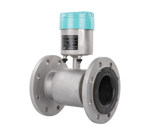
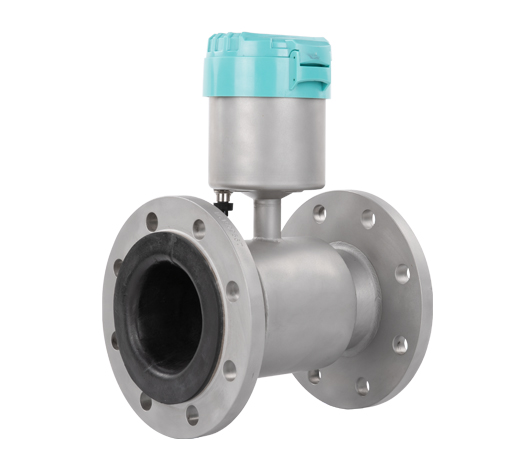
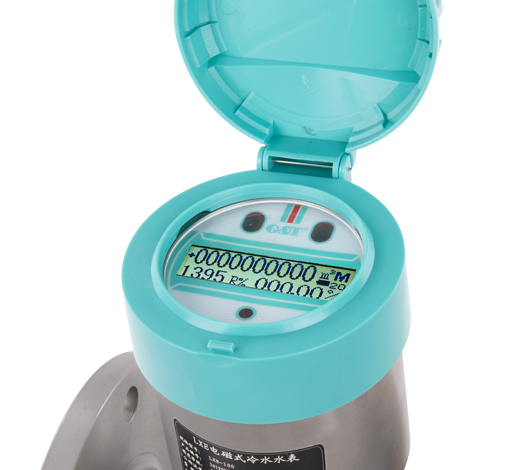
1. The flow direction mark on the sensor must be consistent with the flow direction of the measured medium in the pipeline.
2. The installation position must ensure that the measuring tube is always filled with the measured medium.
3. Select the place where the fluid flow pulse is small, that is, it should be far away from the water pump and local resistance parts (valves, elbows, etc.)
4. When measuring the two-phase fluid, choose the place which is not easy to cause phase separation.
5. Avoid installation in the area with negative pressure in the tube.
6. When the measured medium easily causes the electrode and the inner wall of the measuring tube to adhere to and scale, it is recommended that the flow rate in the measuring tube be no less than 2m/s. At this time, a tapered tube slightly smaller than the process tube can be used. In order to clean the electrode and measuring tube without interrupting the flow in the process tube, the sensor can be installed in parallel with a cleaning port.


Upstream straight pipe section requirements

The requirements of the sensor on the upstream straight pipe section are shown in the table. When the diameters of the upstream and downstream straight pipe sections are inconsistent with those of the electromagnetic cold water meter, the tapered pipe or the tapered pipe should be installed, and its conical Angle should be less than 15° (7° -8 ° is preferred) and then connected with the pipe.
 Upstream resistance 
components

Note: L is straight pipe length
Straight pipe requirements L=0D can be considered as a 
straight pipe section
L≥5D L≥10D
Note :(L is the length of straight pipe section, D is the nominal diameter of sensor)
Send Your Inquiry
Exported to more than 150 countries around the globe, 10000 sets/month production capacity!
Copyright © Q&T Instrument Co., Ltd. All Rights Reserved.
Support: Coverweb