Products
Flange Electromagnetic Flow Meter

Flange Electromagnetic Flow Meter

Size: DN3-DN3000mm
Nominal Pressure: 0.6-1.6Mpa(2.5Mpa/4.0Mpa/6.4Mpa...Max 42Mpa)
Accuracy: +/-0.5%(Standard), 0.3% or 0.2% (Optional)
Liner: PTFE, Neoprene, Hard Rubber, EPDM, FEP, Polyurethane, PFA
Output Signal: 4-20mA/Pulse
Introduction
Application
Technical Data
Installation
Introduction
Electromagnetic flow meter is one of the most popular flow meters. Flange type electromagnetic flow meter has been used for more than 50 years worldwide. It is widely used for all conductive liquids in every industry, such as water, acid, alkali, milk, slurry etc. Since founded in 2005, Q&T has sold more than 600 thousand electromagnetic flow meters to provide the solutions for clients in different work conditions.

 
Advantages
Electromagnetic Flow Meter Advantages and Disadvantages
The main advantages of using electromagnetic flow meter is that it is with no moving parts, no pressure loss and require very less maintenance.
Flange type magnetic flow meter can be made large size range from DN3-DN3000mm and with bi-directional flow measurement. Q&T mag flow meters are with built-in self-diagnosis function and support data record / bluetooth function and various kinds of output signals.

Compared with other liquid type flow meter, the limitations of magnetic flow meter is that it can only be used for conductive liquid.Regarding non or low conductive liquid such as petroleum products, organic solvents can not be used. Electromagnetic flow meter will be affected if there’s strong magnetic filed in the surrounding environment.
Application
Flange Electromagnetic Flow Meter Installation Requirement
Electromagnetic flow meter is widely used in water treatment, food industry, pharmaceutical, petrochemical, paper mill, chemical monitoring etc. 
In the metallurgical industry, it is often used to control the flow of cooling water for continuous steel casting, continuous steel rolling, and steel-making electric furnaces; 
In the field of water supply and drainage in public utilities, electromagnetic flow meters are often used for the transfer measurement of finished product water and raw water in water plants;
In the pulp process of the paper industry, electromagnetic flow meters are involved in the measurement of the flow of grinding pulp, water, acid, and alkali; 
In the coal industry, measuring coal washing and pipeline hydraulic conveying coal slurry.
For food and beverage industries, it is used for beer and beverage filling measurement.
For chemical and petrochemical industries, it is used to measure corrosive liquids, such as acids and alkalis etc
Water Treatment
Water Treatment
Food Industry
Food Industry
Pharmaceutical Industry
Petrochemical
Petrochemical
Paper Industry
Paper Industry
Chemical Monitoring
Chemical Monitoring
Metallurgical Industry
Public Drainage
Public Drainage
Coal Industry
Coal Industry
Technical Data

Table 1:  Flange Magnetic Flow Meter Main Performances Parameters

Size DN3-DN3000mm
Nominal Pressure 0.6-1.6Mpa(2.5Mpa/4.0Mpa/6.4Mpa...Max 42Mpa)
Accuracy +/-0.5%(Standard)
+/-0.3% or +/-0.2%(Optional)
Liner PTFE, Neoprene, Hard Rubber, EPDM, FEP, Polyurethane, PFA
Electrode SUS316L, Hastelloy B, Hastelloy C
Titanium, Tantalum, Platinium-iridium
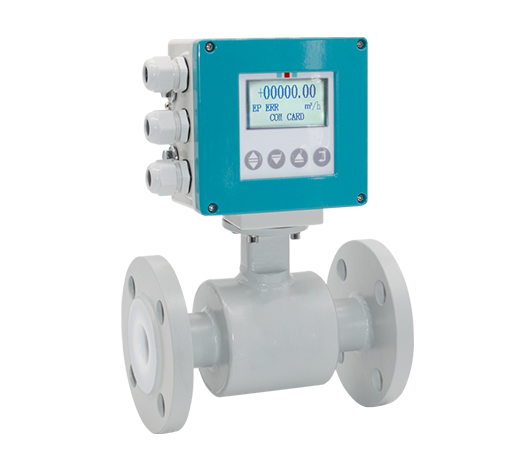
Structure Type Integral type, remote type, submersible type, ex-proof type
Medium Temperature -20~+60 degC(Integral type)
Remote type(Neoprene,Hard Rubber,Polyurethane,EPDM) -10~+80degC
Remote type(PTFE/PFA/FEP) -10~+160degC
Ambient Temperature -20~+60deg C
Ambient Humidity 5-100%RH(relative humidity)
Measuring Range Max 15m/s
Conductivity >5us/cm
Protection Class IP65(Standard); IP68(Optional for remote type)
Process Connection Flange (Standard), Wafer, Thread, Tri-clamp etc (Optional)
 
Output Signal 4-20mA/Pulse
Communication RS485(Standard), HART(Optional),GPRS/GSM (Optional)
Power Supply AC220V (can be used for AC85-250V)
DC24V (can be used for DC20-36V)
DC12V (optional), Battery Powered 3.6V (optional)
Power Consumption <20W
Alarm Upper Limit Alarm / Lower Limit Alarm
Self-diagnosis Empty Pipe Alarm, Exciting Alarm
Explosion Proof ATEX

Table 2:  Flange Magnetic Flow Meter Electrode Material Selection

Electrode Material Applications & Properties
SUS316L Applicable to industrial/municipal water, wastewater and low corrosive mediums.
Widely used in petroleum, chemical industries.      
Hastelloy B Strong resistance to hydrochloric acids below the boiling point.
Resist against oxidable acids, alkali and non-oxidable salts. For instance, vitriol, phosphate, hydrofluoric acids, and organic acids.
Hastelloy C Exceptional resistance to strong solutions of oxidizing salts and acids. For example, Fe+++, Cu++, Nitric acids, mixed acids
Titanium Titanium can withstand corrosive mediums such as seawater, chloride salt solutions, hypochlorite salts, oxidable acids(including fuming nitric acids), organic acids, and alkali.
Not resistant to high purity reducing acids such as sulphuric acids, hydrochloric acids. 
Tantalum Highly resistant to corrosive mediums.
Applicable to all chemical mediums except Hydrofluoric Acids, Oleum and Alkali.
Platinum-iridium Applicable to all chemical mediums except for Ammonium salts and Fortis

Table 3:  Flange Magnetic Flow Meter Flow Range

Size Flow Range & Velocity Table
(mm) 0.1m/s 0.2m/s 0.5m/s 1m/s 4m/s 10m/s 12m/s 15m/s
3 0.003 0.005 0.013 0.025 0.102 0.254 0.305 0.382
6 0.01 0.02 0.051 0.102 0.407 1.017 1.221 1.526
10 0.028 0.057 0.141 0.283 1.13 2.826 3.391 4.239
15 0.064 0.127 0.318 0.636 2.543 6.359 7.63 9.538
20 0.113 0.226 0.565 1.13 4.522 11.304 13.56 16.956
25 0.177 0.353 0.883 1.766 7.065 17.663 21.2 26.494
32 0.289 0.579 1.447 2.894 11.575 28.938 34.73 43.407
40 0.452 0.904 2.261 4.522 18.086 45.216 54.26 67.824
50 0.707 1.413 3.533 7.065 28.26 70.65 84.78 105.98
65 1.19 2.39 5.97 11.94 47.76 119.4 143.3 179.1
80 1.81 3.62 9.04 18.09 72.35 180.86 217 271.3
100 2.83 5.65 14.13 28.26 113.04 282.6 339.1 423.9
125 4.42 8.83 22.08 44.16 176.63 441.56 529.9 662.34
150 6.36 12.72 31.79 63.59 254.34 635.85 763 953.78
200 11.3 22.61 56.52 113.04 452.16 1130.4 1356 1696
250 17.66 35.33 88.31 176.53 706.5 1766.25 2120 2649
300 25.43 50.87 127.2 254.34 1017 2543.4 3052 3815
350 34.62 69.24 173.1 346.19 1385 3461.85 4154 5193
400 45 90 226.1 452 1809 4522 5426 6782
450 57 114 286.1 572 2289 5723 6867 8584
500 71 141 353.3 707 2826 7065 8478 10598
600 102 203 508.7 1017 4069 10174 12208 15260
700 138 277 692.4 1385 5539 13847 16617 20771
800 181 362 904.3 1809 7235 18086 21704 27130
900 229 458 1145 2289 9156 22891 27469 34336
1000 283 565 1413 2826 11304 28260 33912 42390
1200 407 814 2035 4069 16278 40694 48833 61042
1400 554 1108 2769 5539 22156 55390 66468 83084
1600 723 1447 3617 7235 28938 72346 86815 108518
1800 916 1831 4578 9156 36625 91562 109875 137344
2000 1130 2261 5652 11304 45216 113040 135648 169560
2200 1368 2736 6839 13678 54711 136778 164134 205168
2400 1628 3256 8139 16278 65111 162778 195333 244166
2600 1910 3821 9552 19104 76415 191038 229245 286556
2800 2216 4431 11078 22156 88623 221558 265870 332338
3000 2543 5087 12717 25434 101736 254340 305208 381510
Remark:Suggest flow velocity range 0.5m/s - 15m/s
 

Table 4:  Flange Magnetic Flow Meter Selection Guide

QTLD xxx x x x x x x x x
Caliber DN3mm-DN3000mm                  
Nominal Pressure 0.6Mpa 1
1.0Mpa 2
1.6Mpa 3
4.0Mpa 4
Other 5
Connection Mode Flange connection 1
Clamp connection 2
Sanitary connection 3
Liner Material PTFE 1
PFA 2
Neoprenen 3
Polyurethane 4
Ceramic 5
Electrode Material 316L 1
Hastelloy B 2
Hastelloy C 3
Titanium 4
Platinum-iridium 5
Tantalum 6
Stainless steel covered with tungsten carbide 7
Structure Type Integral type 1
Remote type 2
Remote type immerse 3
Integral type Ex-proof 4
Remote type Ex-proof 5
Power 220VAC 50Hz E
24VDC G
Output communication Flow volume 4-20mADC/pulse A
Flow volume 4-20mADC/RS232C communication B
Flow volume 4-20mADC/RS485 communication C
Flow volume HART output/with communication D
Converter Figure Square A
Circular B
 
Installation
Flange Electromagnetic Flow Meter Installation Requirement
In order to obtain a stable and accurate flow measurement, it is very important that the flow meter is installed correctly in the pipe system.
Do not install the meter near equipment that produces electrical interference such as electric motors, transformers, variable frequency, power cables etc.
Avoid locations with pipe vibrations for example pumps.
Do not install the meter close to pipeline valves, fittings or impediments which can cause flow disturbances.
Place the meter where there is enough access for installation and maintenance tasks.
lnstall at the lowest point and vertical upward direction
Don't install at the highest point or vertical downward diection
When drop is more than 5m, install exhaust
valve at the downstream
lnstall at the lowest point when used in open drain pipe
Need 10D of upstream and 5D of downstream
Dont' install it at the entrance of pump, install it at the exit of pump
lnstall at the rising direction
Send Your Inquiry
Exported to more than 150 countries around the globe, 10000 sets/month production capacity!
Copyright © Q&T Instrument Co., Ltd. All Rights Reserved.
Support: Coverweb