Products
Position :
Vertical Display Variable Area Flowmeter

Vertical Display Variable Area Flowmeter

Range ratio: 10:1(Special type 20:1)
Accuracy class: 2.5(Special type 1.5% or 1.0%)
Working pressure: DN15~DN50 PN16 (Special type 2.5MPa)
Medium temperature: Normalized type -80℃~+220℃
Ambient temperature: -40℃~+120℃(Remote display without LCD≤85℃).
Introduction
Application
Technical Data
Installation
Introduction
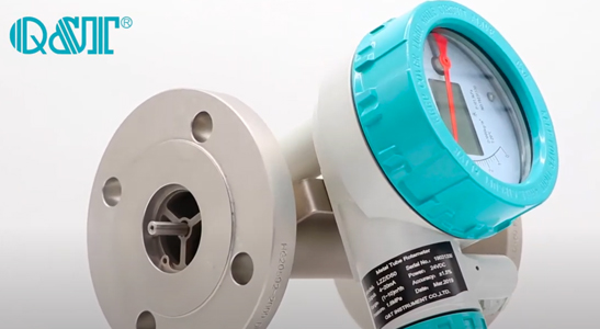
LZ series intelligent Vertical Display Variable Area Flowmeter adopts the international advanced Honeywell without contact and no hysteresis detecting changes in the Angle of magnetic field of magnetic sensor, and with high performance MCU,which can realize LCD display:the instantaneous flow, total flow,loop current.environment temperature,damping time,small signalremoval.Optional 4~20mA tranmission(with HART communication),pulse output, high and low limit alarm output function,etc,the type of intelligent signal transmitter has high precision and reliability,which can fully replace the same type imported instrument, and it also has high price performance, parameter standardization online and power failure protection,etc features.
 
Advantages
Vertical Display Variable Area Flowmeter advantages:
1. Fully welded stainless steel body,Durable using. 
2. Independent of medium’s physical and chemical states such as conductivity, dielectric constants, etc. 
3. Applicable for all kinds of medium environment such as corrosive, toxic and explosive one. 
4. Interface measurement or level measurement of 2 kinds of medium with different density. 
5.Easy-to-read displays on all flow meter types.
6.Two-wire 4~20mADC signal output available.
Application
Vertical Display Variable Area Flowmeter Applications
Vertical Display Variable Area Flowmeter is mainly suitable for small and medium flow measurement of single-phase liquid or gas with small and medium pipe diameter, low noise and Reynolds number of acetic acid,like Air,Water,lubricating oil,Steam,Hydrogen,O2,etc,and many other Liquid or gas in the Chemical,Pharmaceutical, Petrochemical,Food,Metallurgical Industry ,etc.
Water Treatment
Water Treatment
Food Industry
Food Industry
Pharmaceutical Industry
Petrochemical
Petrochemical
Paper Industry
Paper Industry
Chemical Monitoring
Chemical Monitoring
Metallurgical Industry
Public Drainage
Public Drainage
Coal Industry
Coal Industry
Technical Data

Table 1: Vertical Display Variable Area Flowmeter Data Sheet

Measuring range

 Water (20℃)                  16~150000 l/h.

 Air(0.1013MPa 20℃)       0.5~4000 m3/h.

 Range ratio  10:1(Special type 20:1).
 Accuracy class  2.5(Special type 1.5% or 1.0%).
 Working pressure

 DN15~DN50 PN16 (Special type 2.5MPa).

 DN80~DN150 PN10 (Special type 1.6MPa).

 Pressure rating of jacket 1.6MPa.

 Medium temperature

 Normalized type -80℃~+220℃.

 High-temperature type 300℃.    Lined with FEP type ≤85℃.

 Ambient temperature

 -40℃~+120℃(Remote display without LCD≤85℃).

 (Remote display with LCD≤70℃).

 Dielectric viscosity

 1/4” NPT, 3/8” NPT 1/2” NPT≤5mPa.s

 3/4” NPT,1” NPT ≤250mPa.s

 Output

 Standard signal: two-wire system 4 ~ 20mA (with HART communication).

 Standard signal: three-wire system 0 ~ 10mA.

 Alarm signal:1.Two-way relay output.

                    2.One-way or two-approach switches .

 Pulse signal output: 0-1KHz isolated output.

 Process connection

 Standard type:24VDC±20%.

 AC type:220VAC(85~265VAC) (optional).

 Connection mode

 Flange

 Thread

 Tri-clamp

 Levels of protection

 IP65/IP67.

 Ex-mark

 Intrinsically safe:ExiaIICT3~6.    Exd type:ExdIICT4~6.

Table 2: Vertical Display Variable Area Flowmeter Flow Range

Caliber

(mm)

Work number Flow range Pressure loss kpa

Water L/h 

Air m3/h Water Kpa Air
Normal type Anti-corrossion type Normal type
Anti-corrossion type

Normal type

Anti-corrossion type
15 1A 2.5~25 -- 0.07~0.7 6.5 - 7.1
1B 4.0~40 2.5~25 0.11~1.1 6.5 5.5 7.2
1C 6.3~63 4.0~40 0.18~1.8 6.6 5.5 7.3
1D 10~100 6.3~63 0.28~2.8 6.6 5.6 7.5
1E 16~160 10~100 0.48~4.8 6.8 5.6 8.0
1F 25~250 16~160 0.7~7.0 7.0 5.8 10.8
1G 40~400 25~250 1.0~10 8.6 6.1 10.0
1H 63~630 40~400 1.6~16 11.1 7.3 14.0
25 2A 100~1000 63~630 3~30 7.0 5.9 7.7
2B 160~1600 100~1000 4.5~45 8.0 6.0 8.8
2C 250~2500 160~1600 7~70 10.8 6.8 12.0
2D 400~4000 250~2500 11~110 15.8 9.2 19.0
40 4A 500~5000 300~3000 12~120 10.8 8.6 9.8
4B 600~6000 350~3500 16~160 12.6 10.4 16.5
50 5A 630~6300 400~4000 18~180 8.1 6.8 8.6
5B 1000~10000 630~6300 25~250 11.0 9.4 10.4
5C 1600~16000 1000~10000 40~400 17.0 14.5 15.5
80 8A 2500~25000 1600~16000 60~600 8.1 6.9 12.9
8B 4000~40000 2500~25000 80~800 9.5 8.0 18.5
100 10A 6300~63000 4000~40000 100~1000 15.0 8.5 19.2
150 15A 20000~100000 -- 600~3000 19.2 -- 20.3

Table 3: Vertical Display Variable Area Flowmeter Model Selection

QTLZ X X X X X X X X X
Indicator Code                
Local indicator Z
LCD indicator with ouput D
Norminal diameter Code
DN15 -15
DN20 -20
DN25 -25
DN40 -40
DN50 -50
DN80 -80
DN100 -100
DN150 -150
Structure Code
Bottom-top /
Left-right (horizontal) H1
Right-left (horizontal) H2
Side-side AA
Bottom -side LA
Thread connection S
Tri-clamp M
Body material Code
304SS R4
316LSS R6L
Hastelloy C Hc4
Titanium Ti
Liner F46(PTFE) F
Monel M
Indicator type Code
Iinear indicator(pointer indication) M7
Nonlinear indicator(LCD Display) M9
Combination function(only for LCD display) Code
24VDC with 4~20mA output S
24VDC with HART communication Z
Battery power D
Additional function Code
Measuring tube with thermal preservation / heat insulation jacket T
Measure medium temperature higher than 120.C HT
Ex-proof: Code
With W
Without N
Alarm Code
One alarm K1
Two alarm K2
None N
Installation
Metal Tube Rotameter Installaion
Installed flowmeter should guarantee the entry ≥5DN straight pipe section,export straight pipe section not less than 250mm ;if the medium containing ferromagnetic material,magnetic filter should be installed in front of the flowmeter。(see magnetic  filter  and straight pipe section diamension diagram )

1. For flow meter installed,ensure the measuring pipe perpendicularity is better than 5 and should be equipped with bypass,easy to maintain and clean and does not affect production..
2. Monitoring and control system in the control valve,should be installed downstream of the flowmeter.For gas measurement,Should ensure the working pressure is not less than 5 times of pressure loss of the flowmeter, to make stable work of the flowmeter.
3. Before install the flowmeter,The pipe should be welding slag purging clean;When installation to remove locking component in the flow meter;when used after installation,Slowly open the control valve,Avoid shock damage  flow meter
Send Your Inquiry
Exported to more than 150 countries around the globe, 10000 sets/month production capacity!
Copyright © Q&T Instrument Co., Ltd. All Rights Reserved.
Support: Coverweb