Products
Position :
Gas Roots Flow Meter

Gas Roots Flow Meter

Nominal Diameter: DN25-DN200mm
Nominal Pressure: 1.6Mpa/2.5Mpa/4.0Mpa
Low startup flow: 0.05~0.95m3/h
Accuracy: 1.5% (Standard), 1.0% (Optional)
Repeatability: Better than 0.2%
Introduction
Application
Technical Data
Installation
Introduction
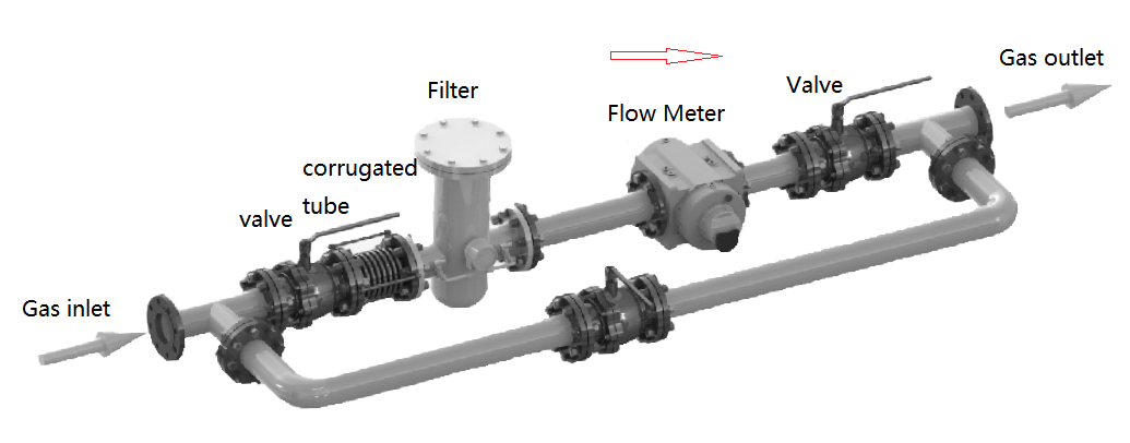
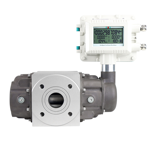
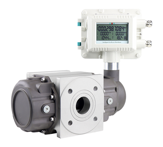
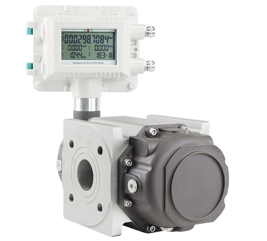
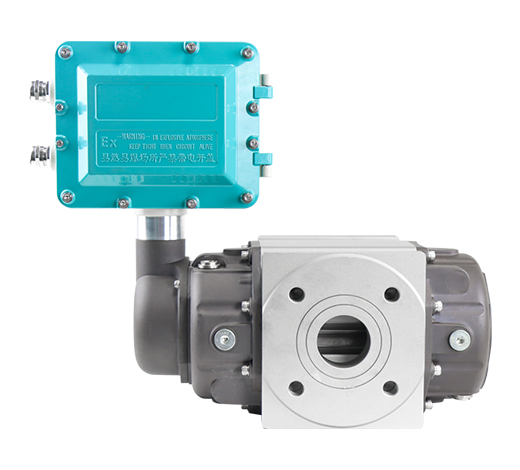
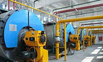
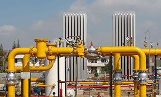
QTLL intelligent gas roots flow meter is a flow meter that integrates flow, pressure and temperature detection functions which could perform pressure, temperature and compression factor correction. It has a variety of structural forms and functional configurations to meet the different requirements of users. QTLL gas roots flow meter is widely used in the fields of urban gas and industrial gas flow measurement and detection, and could meet the user's requirements for high-precision, high-reliability measurement or detection.
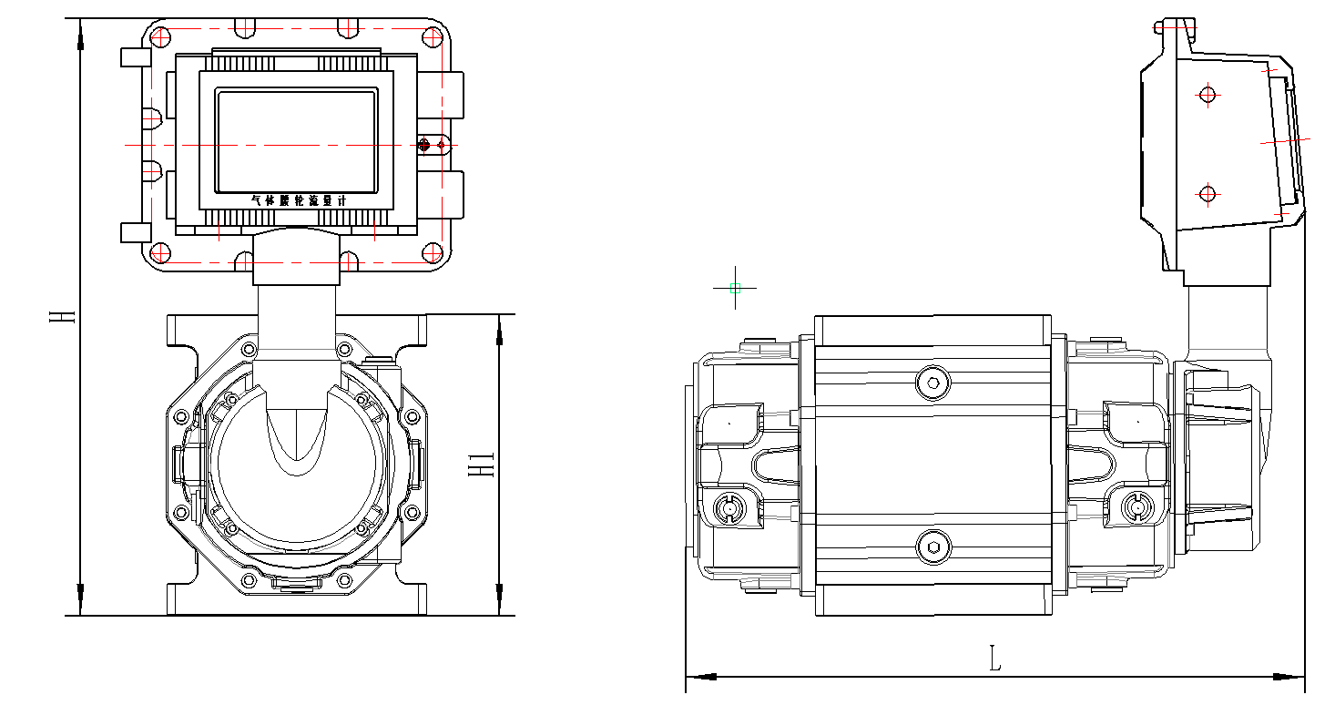
 
Advantages
Gas roots flow meter is with high accuracy and good repeatability, it adopt high-precision imported dust-proof stainless steel special bearings which could ensure long service life. The intelligent integrated design can dynamically detect the temperature and pressure, and perform automatic compensation and compression factor correction. With advanced dual-power micro-power consumption technology, gas roots flow meter support battery working life more than 3years. 
Compared with precession vortex flow meter, gas turbine flow meter is with low pressure loss, low initiating flow and wider range ratio. 
 
Application
Gas roots flow meter is widely used in the flow measurement of natural gas, coal-to-gas, inert gas, air and other gases. It is an ideal flow measurement device for domestic and foreign urban gas, oilfield chemical, scientific research and other departments.
Natural Gas
Natural Gas
Petroleum
Petroleum
Chemical
Chemical
Electric Power
Electric Power
Industrial Boilers
Industrial Boilers
Gas Metering
Gas Metering
Technical Data

Gas Roots Flow Meter Parameters

Size DN25-DN200mm
Accuracy 1.5% (Standard)  Qt—Qmax ±1.5%,Qmin—Qt ±3.0%,Qt=0.05Qmax
1.0% (Optional)   Qt—Qmax ±1.5%,Qmin—Qt ±3.0%,Qt=0.05Qmax
Repeatability Better than 0.2%
Working condition Ambient: -30℃~+60℃
Medium temperature:-20℃~+80℃
Relative humidity: 5%-9%
Power supply External power: +12~24VDC
Internal power:3.6V Battery
Power consumption <2W (external power)
≤1mW (internal power)
Output Pulse
4-20mA (external power)
Communication RS485
Pressure rating 1.6MPa

Gas Roots Flow Meter Dimension

Model Flow Spec L H1 H Remark
QTLL-25 G16 273 128 340 Flange dimension refer to PN1.6MPa GB flange.
Other flange standards can specially make.
While installation, please consider the sealing gasket thickness about 2-3mm.
QTLL-40 G25 354 190 375
QTLL-50 G25 354 190 375
G40 425 190 375
G65 425 190 375
QTLL-80 G65 412 190 375
G100 412 190 375
G160 475 245 400
QTLL-100 G160 575 245 400
G250 665 245 400
QTLL-150 G400 683 460 505
G650 802 460 505

Gas Roots Flow Meter Flow Range

Model Flow Spec
Size
(mm)
Flow Range
(m³/h)
Start up flow
(m³/h)
Max Pressure loss
(KPa)
QTLL-25 G16 DN25 1-25 0.05 0.08
QTLL-40 G25 DN40 1-40 0.05 0.08
QTLL-50 G25
DN50
1-40 0.1 0.08
G40 2-65 0.1 0.1
G65 2-100 0.12 0.15
QTLL-80 G65
DN80
2-100 0.12 0.15
G100 2.5-160 0.1 0.15
G160 3-250 0.1 0.18
QTLL-100 G160 DN100 3-250 0.1 0.2
G250 4-500 0.65 0.35
QTLL-150 G400 DN150 8-650 0.76 0.46
G650 15-1000 0.85 0.5
QTLL-200 G1600 DN200 32-1600 0.95 0.6

Gas Roots Flow Meter Model Selection

QTLL  Parameters ××× × × × × × ×
Size (mm) DN25-DN200mm              
Accuracy 1.5% (standard) 1
1.0% 2
Nominal Pressure 1.0MPa 1
1.6MPa 2
Others 3
Body Material Aluminum Alloy A
Stainless Steel S
Output/
Communication
Pulse 1
Pulse+4~20mA 3
Pulse+4~20mA+RS485 4
Power Supply Battery Powered 1
Battery Powered + External Power DC24V 2
Ex-proof With 1
Without 2
Installation Horizontal H
Vertical V
Installation
Installation Requirement for Gas Roots Flow Meter
Before the flow meter is installed (especially the new pipeline or the pipeline after repair), the pipeline must be purged to remove impurities such as welding slag and rust.

(1)Vertical installation
When installing vertically, the gas inlet should be at the top, and the airflow will flow from top to bottom, that is, top in and bottom out. The company recommends users to use vertical installation as much as possible. The self-cleaning ability of the rotor to sundries;
(2)Horizontal installation
When installing horizontally, the axis of the inlet and outlet ends of the flow meter should not be lower than the axis of the pipeline to prevent impurities in the gas from staying in the flow meter and affecting normal operation. At the same time, the flow meter flange should be directly connected to the filter flange;
(3) Regardless of vertical installation or horizontal installation, the rotor shaft in the flow meter must be in a horizontal position.
Send Your Inquiry
Exported to more than 150 countries around the globe, 10000 sets/month production capacity!
Copyright © Q&T Instrument Co., Ltd. All Rights Reserved.
Support: Coverweb