Products
Position :
Liquid Turbine Flow Meter

Liquid Turbine Flow Meter

Accuracy: ±0.5%, ±0.2% Optional
Sensor Material: SS304, SS316L Optional
Signal Output: Pulse, 4-20mA, Alarm(optional)
Digital Communication: MODBUS RS485; HART
Power Supply: 24V DC/3.6V Lithium Battery
Introduction
Application
Technical Data
Installation
Introduction
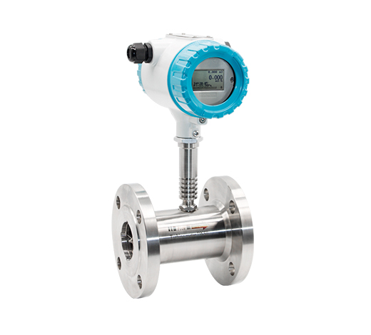
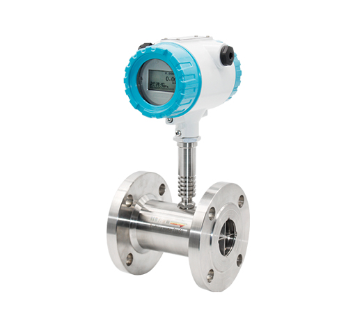
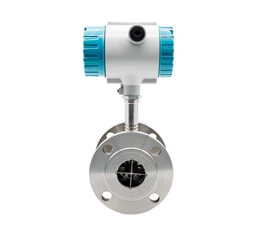
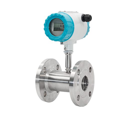
Q&T  Liquid Turbine Flow Meter is internally developed and perfected by Q&T Instrument. Over the years, Q&T Liquid Turbine Flow Meter has been commissioned in many parts of the world, received praise from end-users and industrial leaders. 
Q&T Instrument Turbine Flow Meter offers two accuracy classes, 0.5%R and 0.2%R. Its simple structure allows a small pressure loss and virtually no maintenance requirements.  
The Flange Type Turbine Flow Meter offers two types of converter options, Compact Type (Direct Mount) and Remote Type.  Our users can select the preferred converter type depending on the commissioning environment. 
Advantages
Liquid Turbine Flow Meter Advantages and Disadvantages
Q&T strives to provide high-quality products with economical cost. 
Q&T Liquid Turbine Flow Meter applies to viscous fluids, non-conductive fluids, solvents, liquefied gases and high-pressure applications. 
Q&T Instrument Liquid Turbine Flow Meter provides high accuracy of 0.2% R and a wide range of applications to non-conductive liquids, such as fuel oil, ultrapure water and gasoline. These make the turbine meter more popular compare to Electromagnetic Flow Meter in the oil industry, purifying process and distilleries.  
The Q&T Instrument meter also has an amazingly wide turndown ratio of 20:1, combined with its mechanical designings enables the meter to operate reliably in both high and low flow rates and produce excellent repeatability as low as 0.05%. 
The Flange type connection Turbine Flow Meter is known for its application in oil & gas industry. It is often commissioned in off-shore and onshore oil exploration sites and transportation sites. It is compatibility with high temperature/pressure pipe and high durability makes it the most popular flow instrument in oil and gas industry.
Application
Liquid Turbine Flow Meter Applications
Q&T Instrument Liquid Turbine Flow Meters offers both standard SS304 body and SS316 body.  Because of its wide working temperature and pressure range, it is capable of measuring various mediums and commissioning into extreme working conditions. 
Q&T Instrument Liquid Flow Turbine Meters are popular in the Oil & Gas industry, Chemical industry, and Water industry. The Flange connection version is compatible with High pressure/temperature commission sites. It is the most popular meter in upstream oil production and transportation, off-shore exploration, water supply, and much more. 
Due to its high accuracy and fast response time, Q&T Instrument Liquid Turbine is often integrated into the Industrial Internet of Things, together with valves and pumps to achieve smart process control, for example, solvents batching, blending, storage and off-loading systems. Kindly contact our sales engineers if there are questions related to integrating Q&T Liquid Turbine Meters into your existing plant IOT.
Water Treatment
Water Treatment
Petrochemical
Petrochemical
Chemical Monitoring
Chemical Monitoring
Upstream Oil Transportation
Off-shore Exploration
Water Supply
Water Supply
Technical Data

Table 1: Liquid Turbine Flow Meter Parameters

Size & Process Connection Thread connection:DN4,6,10,15,20,32,40,50,65,80,100
Flange connection:DN15,20,32,40,50,65,80,100,125,200
Clamp connection:DN4,6,10,15,20,32,40,50,65,80,100
Accuracy ±0.5%, ±0.2% Optional
Sensor Material SS304, SS316L Optional
Ambient Conditions Medium temperature:-20℃~+150℃
Atmospheric pressure:86Kpa~106Kpa
Ambient temperature:-20℃~+60℃
Relative humidity:5%~90%
Signal Output Pulse, 4-20mA, Alarm(optional)
Digital Communication RS485, MODBUS; HART
Power Supply 24V DC/3.6V Lithium Battery
Cable Entry M20*1.5; 1/2"NPT
Explosion-proof class Ex d IIC T6 Gb
Protection class IP65; IP67 Optional
 

Table 2: Liquid Turbine Flow Meter Dimension

Diameter Flange Connection
(mm) L(mm) D(mm) K (mm) d (mm) n (Holes) Flange Thickness C (mm)
10 345 90 60 14 4 16
15 75 95 65 14 4 16
20 80 105 75 14 4 18
25 100 115 85 14 4 18
32 120 140 100 18 4 18
40 140 150 110 18 4 19
50 150 165 125 18 4 21
65 175 185 145 18 4 21
80 200 200 160 18 8 23
100 220 220 180 18 8 23
125 250 250 210 18 8 25
150 300 285 240 22 8 25
200 360 340 295 22 12 27

Table 3: Liquid Turbine Flow Meter Flow Range

Diameter
(mm)
Standard Range
(m3/h)
Extended Range
(m3/h)
Connection Standard(Optional) Standard Pressure
(Mpa)
Customized Pressure Rating(Mpa)
DN4 0.04~0.25 0.04~0.4 Thread 6.3 12,16,25...42 
DN6 0.1~0.6 0.06~0.6 Thread 6.3 12,16,25...42 
DN10 0.2~1.2 0.15~1.5 Thread 6.3 12,16,25...42 
DN15 0.6~6 0.4~8 Thread(Flange) 6.3,2.5(Flange) 4.0,6.3,12,16,25...42 
DN20 0.8~8 0.45~9 Thread(Flange) 6.3,2.5(Flange) 4.0,6.3,12,16,25...42 
DN25 1~10 0.5~10 Thread(Flange) 6.3,2.5(Flange) 4.0,6.3,12,16,25...42 
DN32 1.5~15 0.8~15 Thread(Flange) 6.3,2.5(Flange) 4.0,6.3,12,16,25...42 
DN40 2~20 1~20 Thread(Flange) 6.3,2.5(Flange) 4.0,6.3,12,16,25...42 
DN50 4~40 2~40 Thread(Flange) 2.5 4.0,6.3,12,16,25...42 
DN65 7~70 4~70 Flange 2.5 4.0,6.3,12,16,25...42 
DN80 10~100 5~100 Flange 2.5 4.0,6.3,12,16,25...42 
DN100 20~200 10~200 Flange 1.6  4.0,6.3,12,16,25...42 
DN125 25~2500 13~250 Flange 1.6  2.5,4.0,6.3,12,16...42
DN150 30~300 15~300 Flange 1.6  2.5,4.0,6.3,12,16...42
DN200 80~800 40~800 Flange 1.6  2.5,4.0,6.3,12,16...42

Table 4: Liquid Turbine Flow Meter Model Selection

Model Suffix Code Description
LWGY- XXX X X X X X X X X
Diameter                 Three Digitals; for example:
010: 10 mm;              015: 15 mm;
080: 80 mm;              100: 100 mm
Converter N No display; 24V DC; Pulse Output
A No display; 24V DC; 4-20mA Output
B Local display; Lithium Battery Power; No output
C Local display; 24V DC Power; 4-20mA Output;
C1 Local display; 24V DC Power; 4-20mA Output; Modbus RS485 Communication
C2 Local display; 24V DC Power; 4-20mA Output; HART Communication
Accuracy 05 0.5% of Rate
02 0.2% of Rate
Flow Range S Standard Range: refer to flow range table
W Wide Range: refer to flow range table
Body Material S SS304
L SS316
Explosion Rating N Safety Field without Explosion
E ExdIIBT6
Pressuring Rating E Per Standard
H(X) Customized Pressure Rating
Connection -DXX DXX: D06, D10, D16, D25, D40 D06: DIN PN6; D10: DIN PN10 D16: DIN PN16; D25: DIN PN25 D40: DIN PN40
-AX AX: A1, A3, A6
A1: ANSI 150#; A3: ANSI 300#
A6: ANSI 600#
-JX  
-TH Thread; DN4…DN50
Fluid  Temperature -T1 -20...+80°C
-T2 -20...+120°C
-T3 -20...+150°C
Installation
Liquid Turbine Flow Meter Installation and Maintenance
Before the installation, it is crucial to communicate with our sales engineers regarding the working conditions and medium the meter designs to measure. 
The installation of the Q&T Flange Type Liquid Turbine Flow Meter involves minimal effort. During installation, the users will need bolts, nuts, washers and appropriate tools for installation.
The user needs to keep in mind these three factors while carrying out the installation. 
1. There should be at least ten pipe diameter lengths of straight pipe upstream of the Turbine Meter and five pipe diameter length of straight pipe length downstream of the Turbine Meter, with the same nominal diameter size. 
2. Valves and Throttling devices needed to install downstream of the flow meter. 
3. The arrow indicated on the meter body is the same as the actual flow.
If there are specific questions regarding the installation of the Q&T Instrument Turbine Meter, kindly contact our sales engineers for assistance. 
One 90° elbow
Two 90° elbows for two planes
Concentric expander
Control valve half-open
Concentric shrinkage wide open valve
Two 90° elbows for one plane
Q&T Liquid Turbine Flow Meter requires minimum maintenance
Cleaning and inspection of flow meter can be carried out by remove the Turbine Meter from the pipe.
Reinstallations are carried out similarly to the installation steps indicated above.
If the meter is damaged and repair is needed, kindly contact Q&T Instrument Sales Engineers.
 
Send Your Inquiry
Exported to more than 150 countries around the globe, 10000 sets/month production capacity!
Copyright © Q&T Instrument Co., Ltd. All Rights Reserved.
Support: Coverweb